1. Step 1: Hardware setup
Step 1 for setting up the senseBox:home.
Information on the setup & extensions
Since the senseBox is a modular kit, individual steps to sensors may differ or even be skipped in your case. First we show you how to insert the microcontroller into the case.
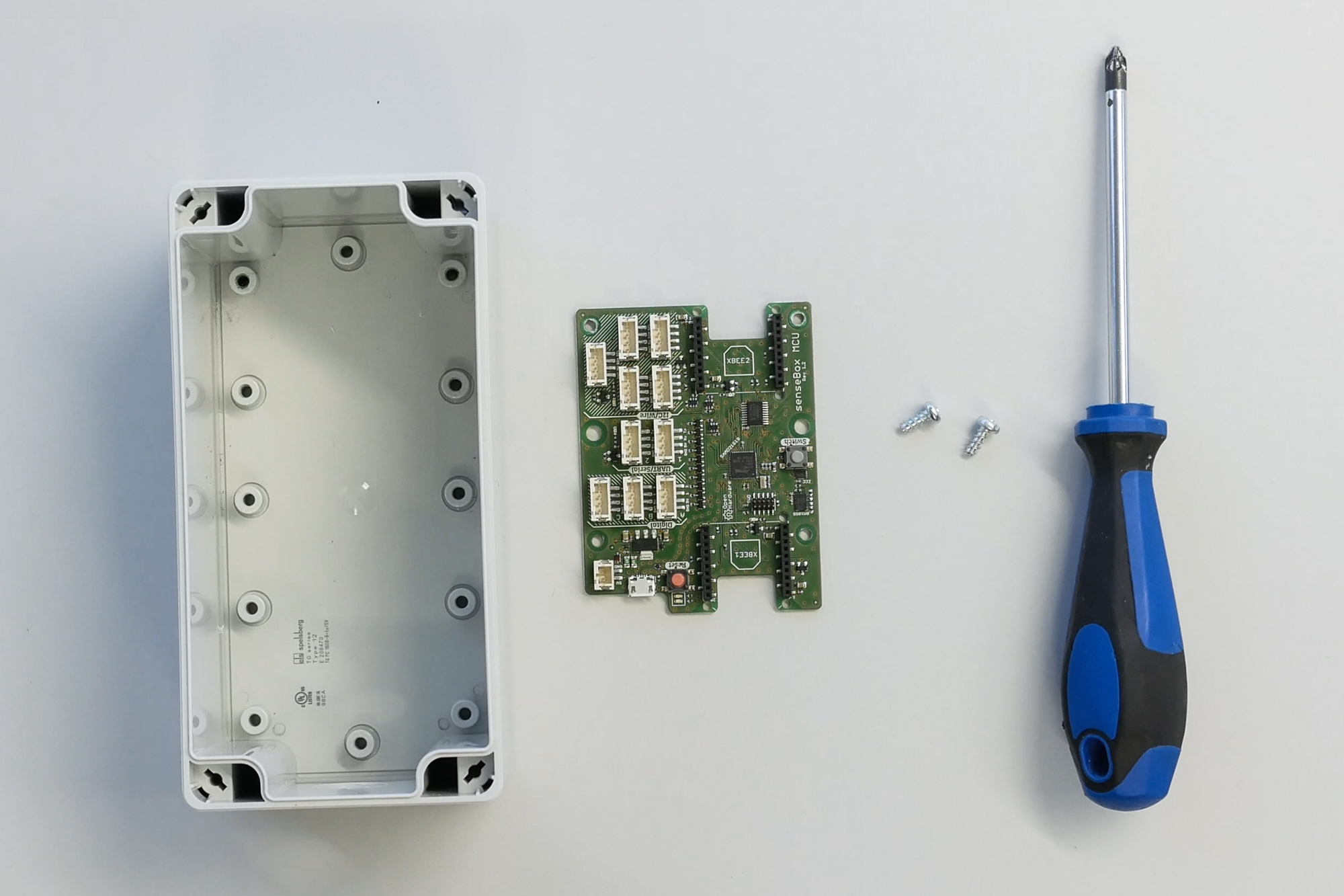
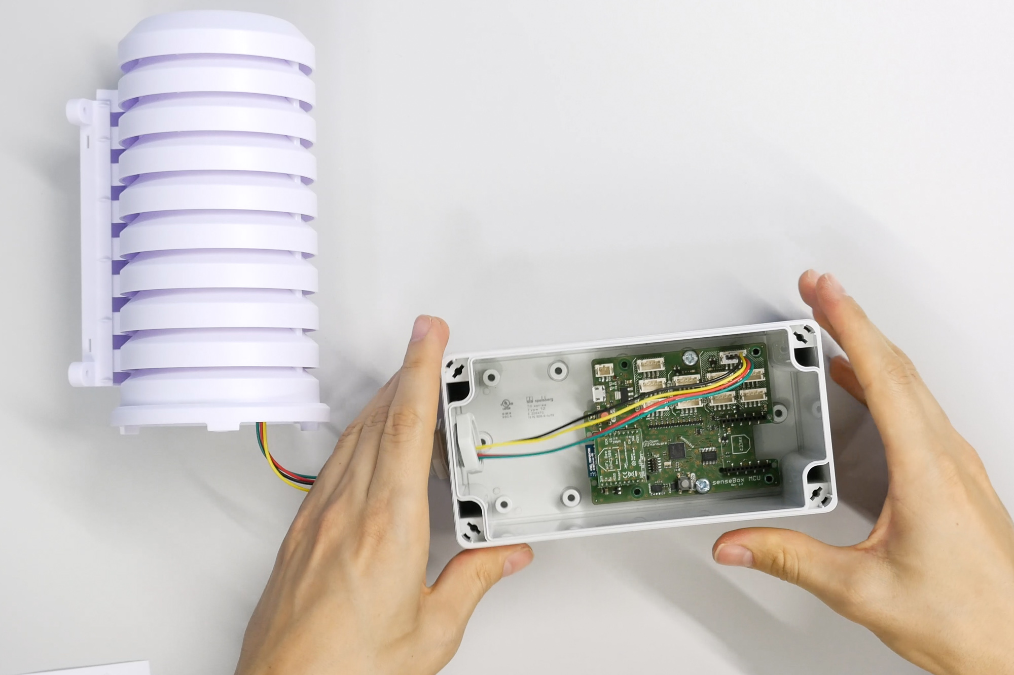
To do this, take the housing and align it with the bore pointing downwards. The green senseBox microcontroller is now placed on the opposite side, so that the red reset button and the USB port are facing the front.
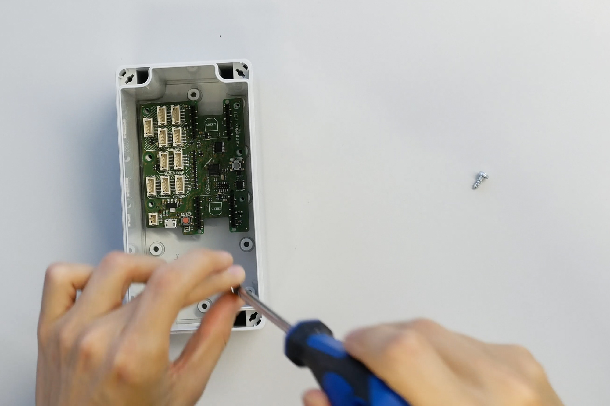
Now you take the two smaller screws included and fix the board to the case via the middle drill holes. If the board has some clearance it is no problem.
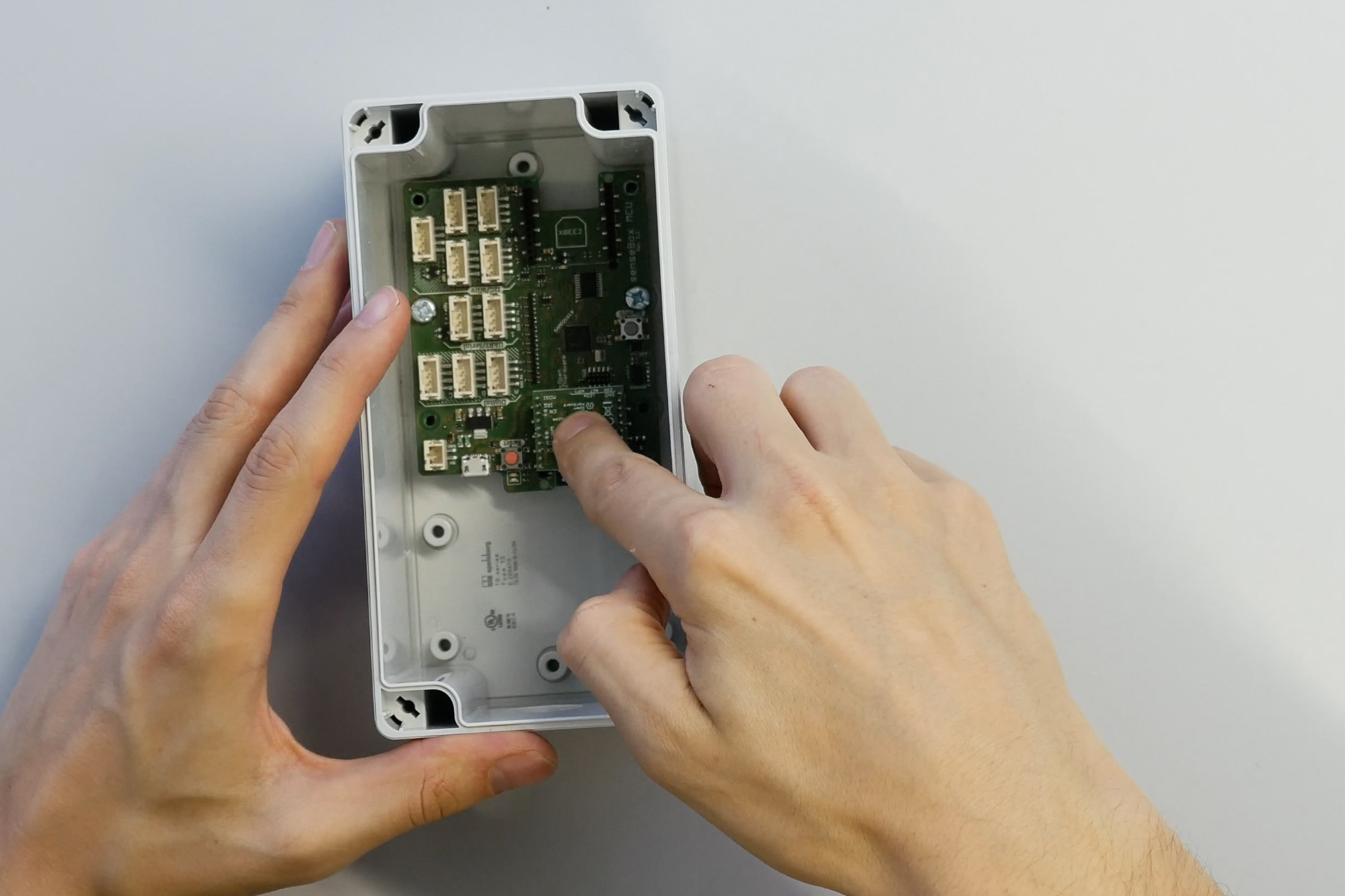
Next we will show how to set up the Wifi-Bee.
We have printed a label on all Bees to indicate the direction. If you have another data transfer module, e.g. LAN, or LoRaWAN, this is exactly the same.
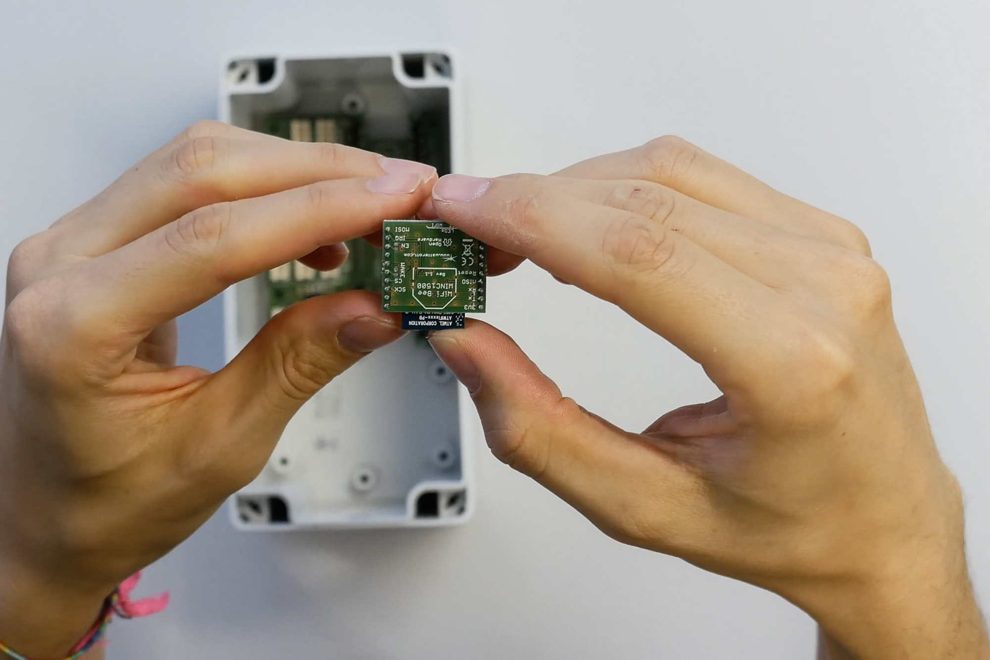
The Wifi-Bee is placed on XBee port 1 and carefully pressed into the baseboard so that all pins of the Bees are inserted.
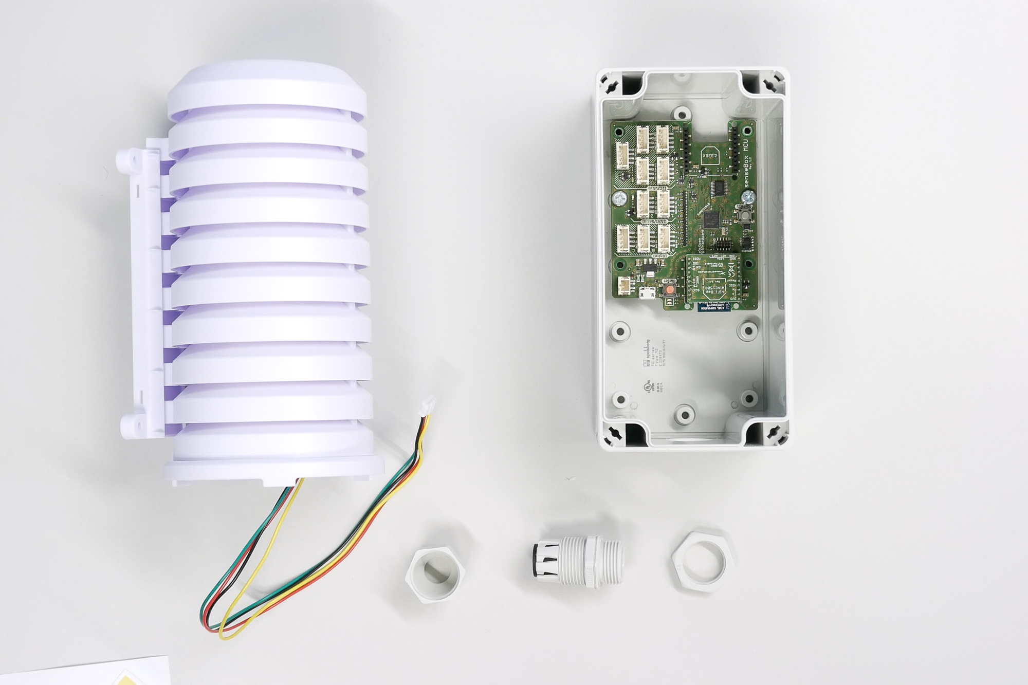
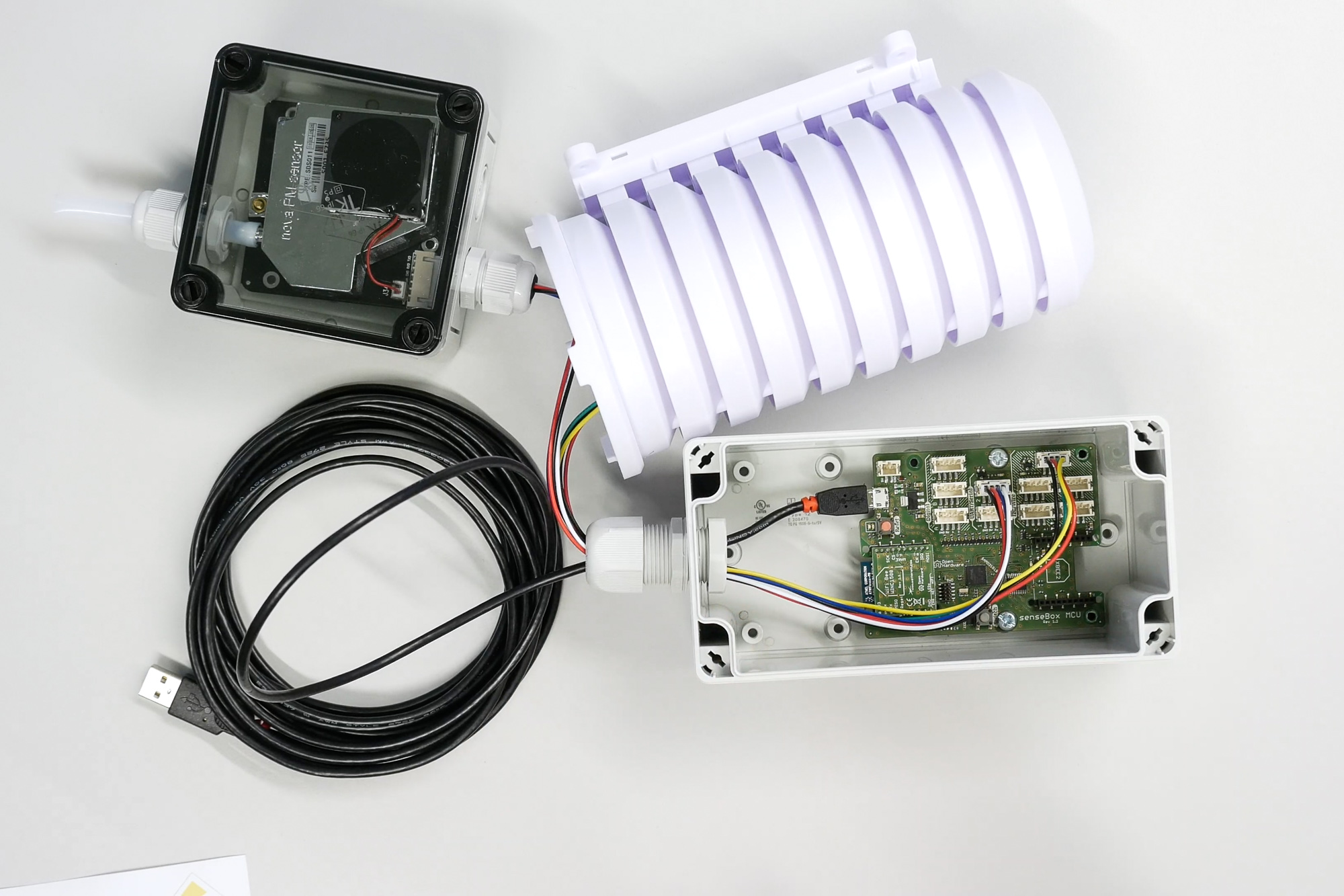
Now we show the construction of the radiation protection housing in which the temperature and humidity sensor is mounted. In the radiation protection there are some mounting parts to mount it later outside. These we do not need for the time being.
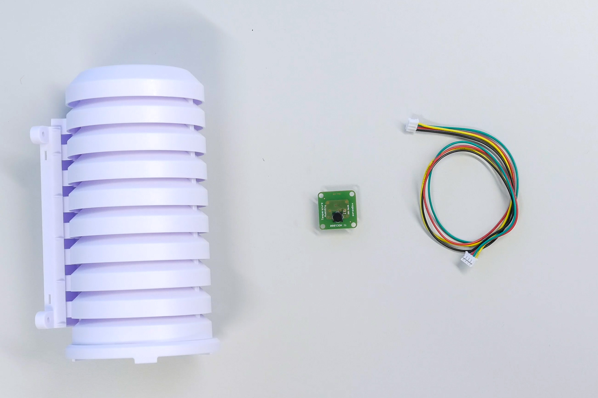
First, a long senseBox cable is pulled through the opening in the base of the radiation shield and the temperature and humidity sensor is plugged in.
The sensor can now also be attached to the stand with some adhesive tape or a cable tie. The radiation protection housing later ensures good air circulation and at the same time protects the sensor from the weather. Now the radiation protection housing can be plugged together and later the sensor is connected to the senseBox microcontroller.
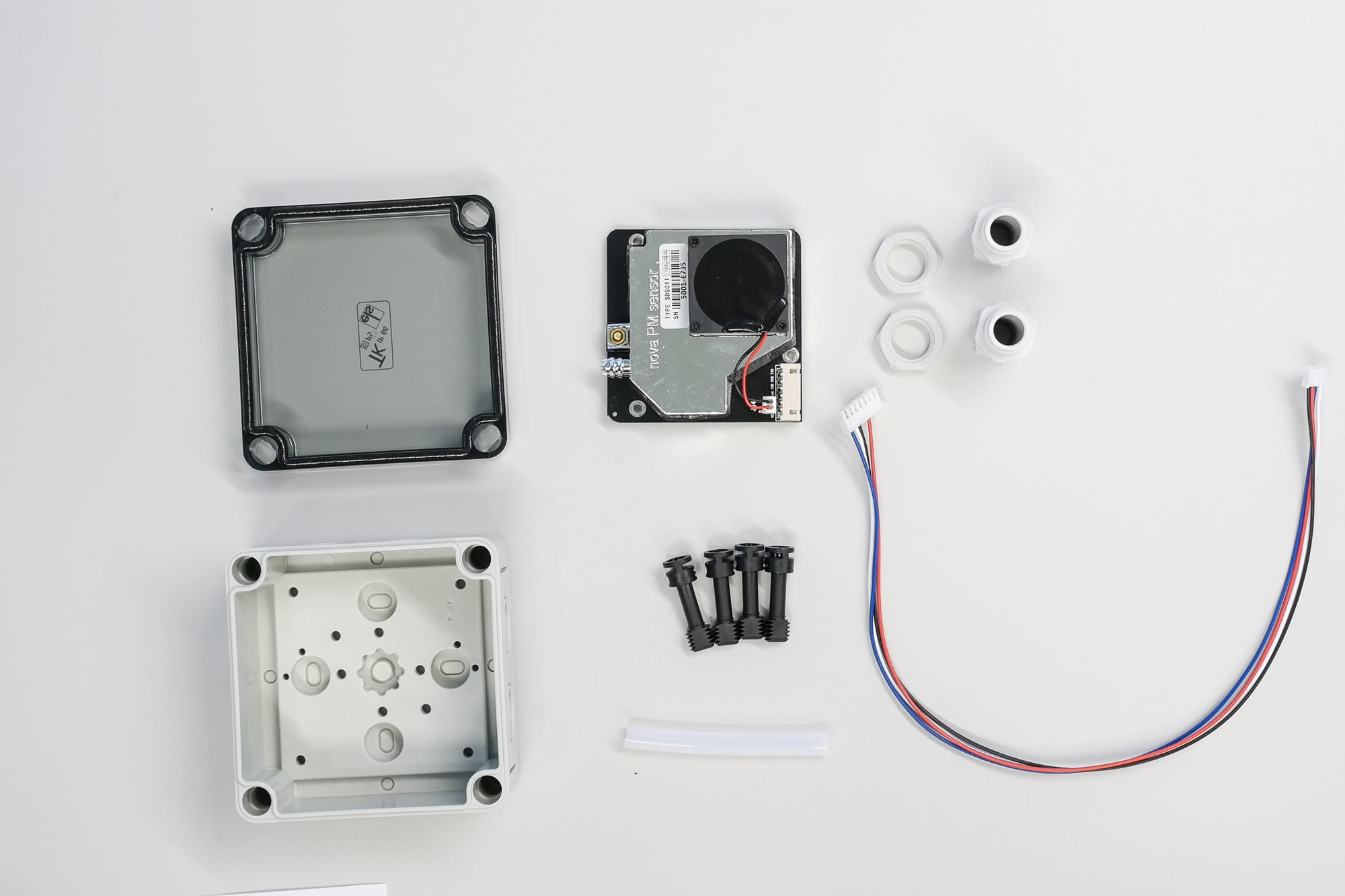
Next we show the setup of the fine dust sensor.
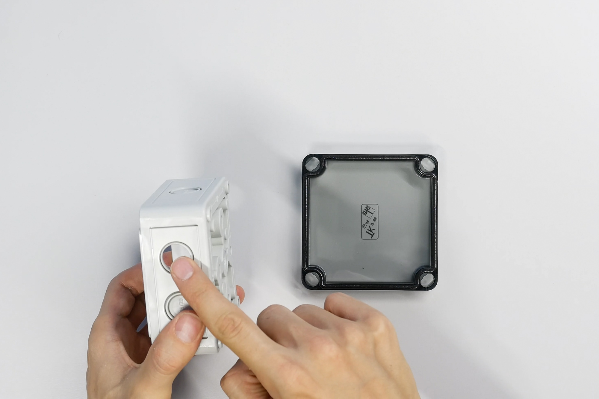
For this purpose, the housing for the sensor must be provided with openings for cables and the air supply. The openings should be opposite each other on the sides with two predetermined breaking points each. For safety reasons we recommend drilling the openings. Theoretically, the openings can also be opened at the predetermined breaking points with a blunt object.
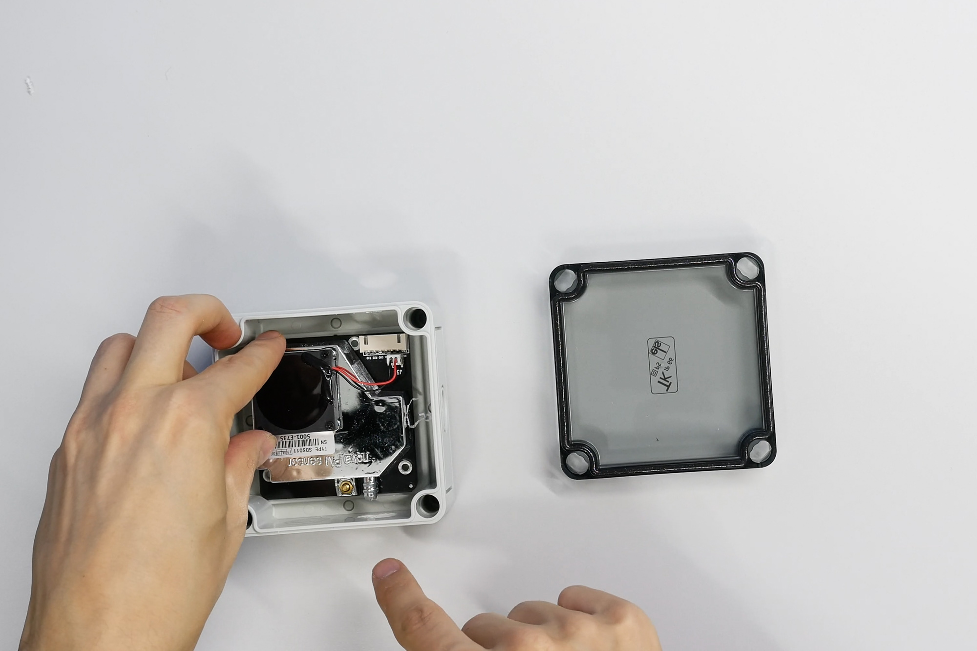
Next, we take the fine dust sensor and place it in the housing so that the cable connection and the air intake socket are at the openings that have just been drilled.
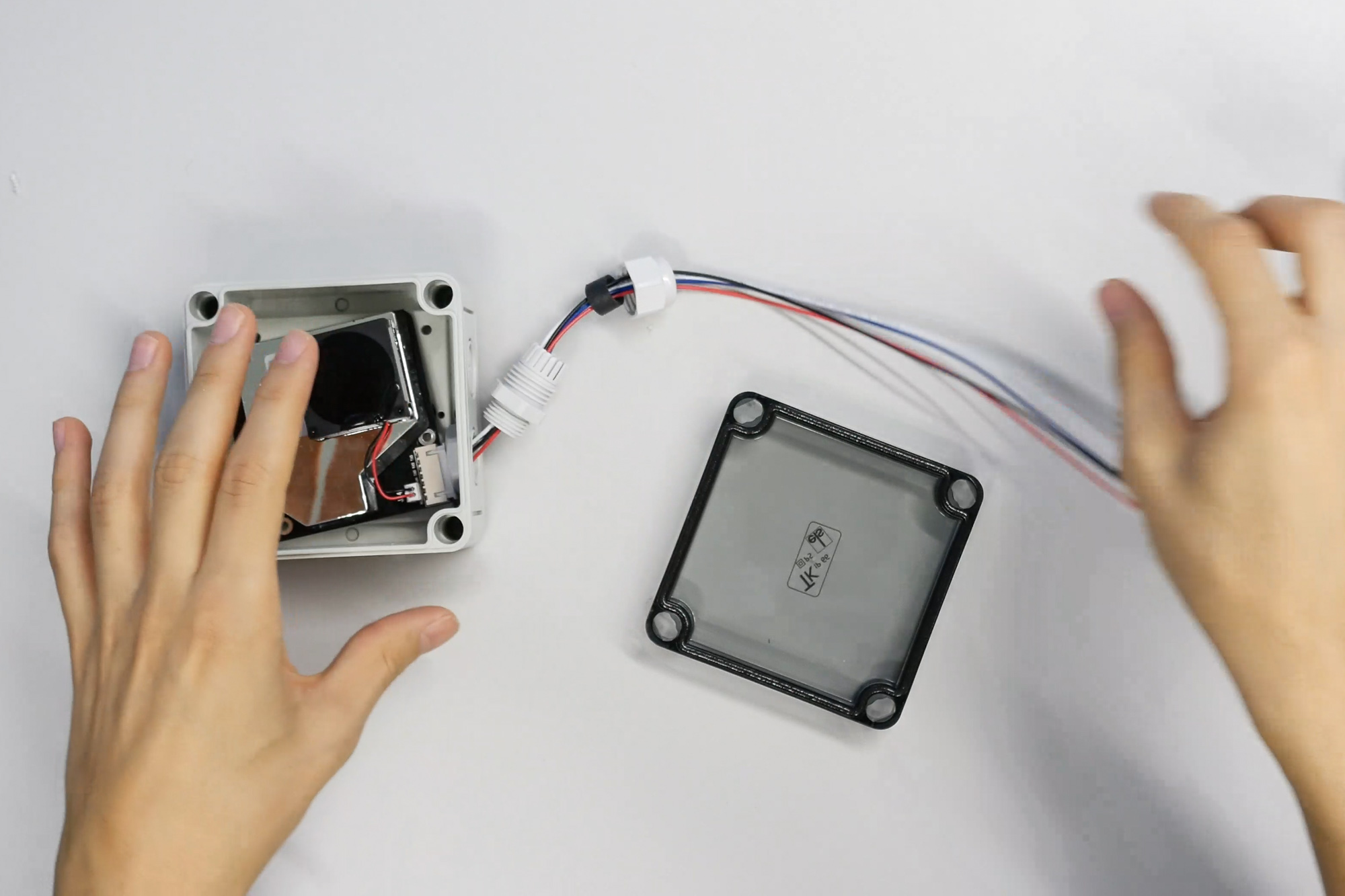
The cable for the fine dust sensor has a different colour and is attached to the sensor with the larger connector.
Then the cable glands for the cable connection are fitted. Simply unscrew the cable gland and then sort the individual parts in the correct order. Then quickly screw them together and that’s it.
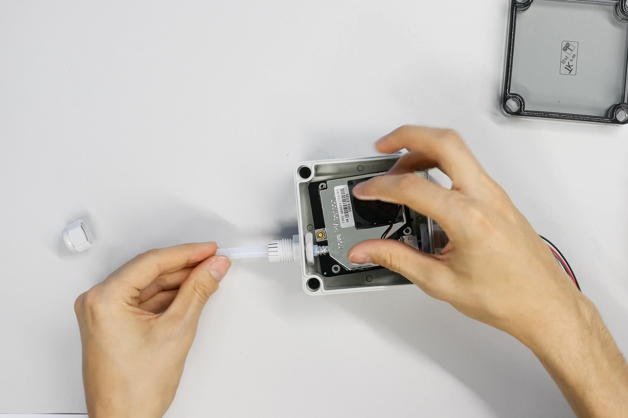
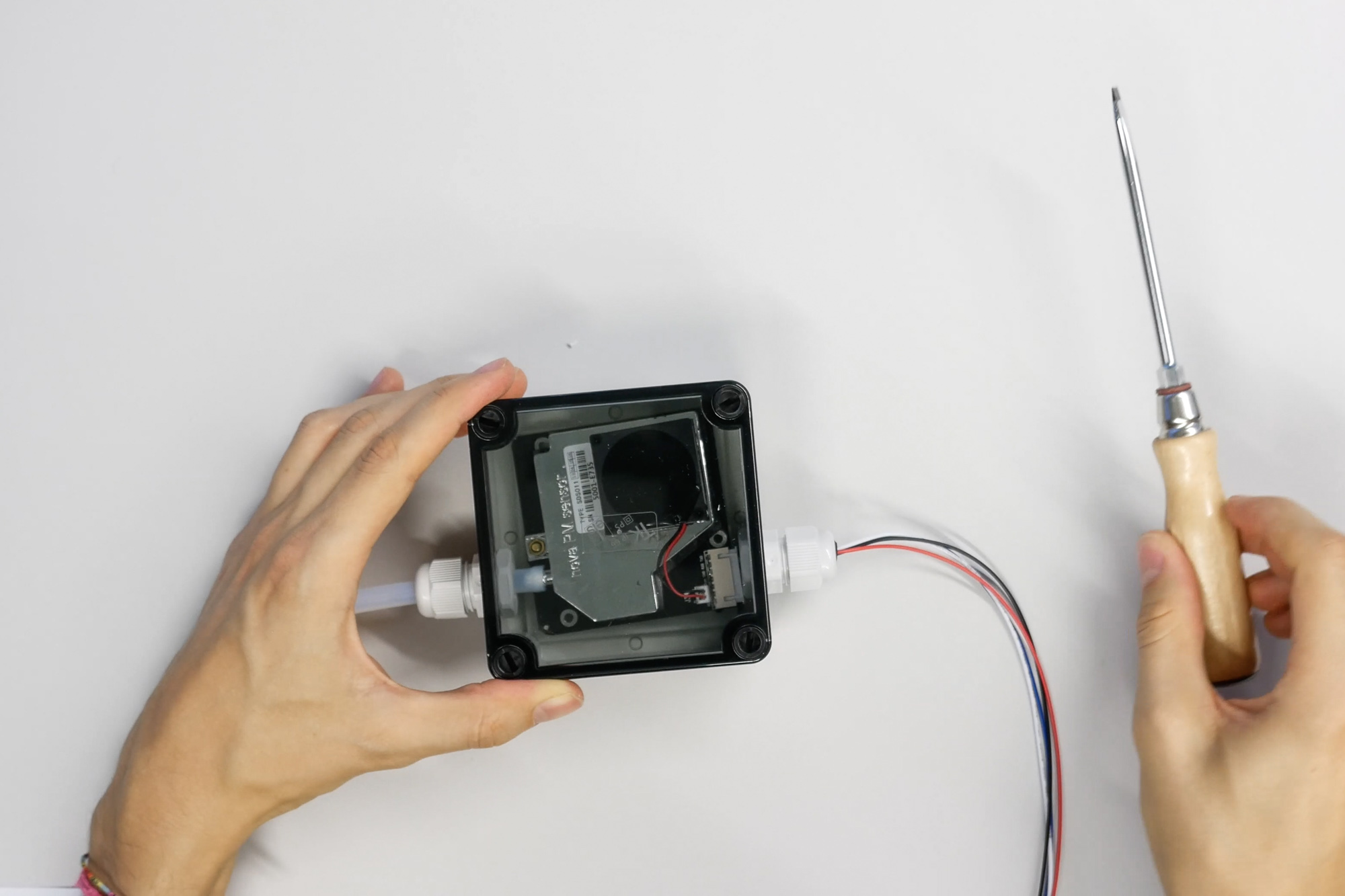
On the other side of the sensor, the hose is now attached to the air intake socket. Here we also use a cable gland to seal the hose. Then we have to sort everything correctly. At the end, some pressure on the tube is necessary to put it on the socket. Finally put on the lid and the fine dust sensor is ready.
The external sensors, i.e. the sensor for temp. and humidity and the fine dust sensor are now connected to the MCU. For this, we first take the cable out of the radiation protection and thread it through the last cable gland into the housing.
There the cable is plugged into one of the slots marked I2C/Wire.
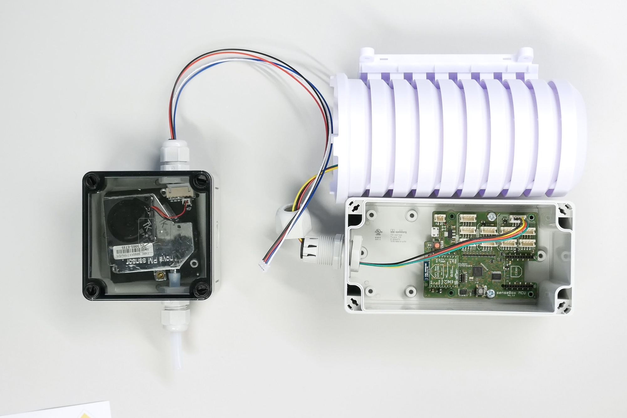
Then the cable is taken out of the fine dust sensor and threaded through the gland. This cable is inserted into one of the slots labeled UART/Serial.
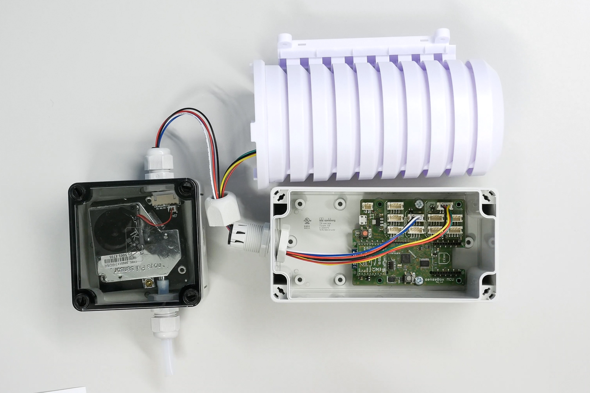
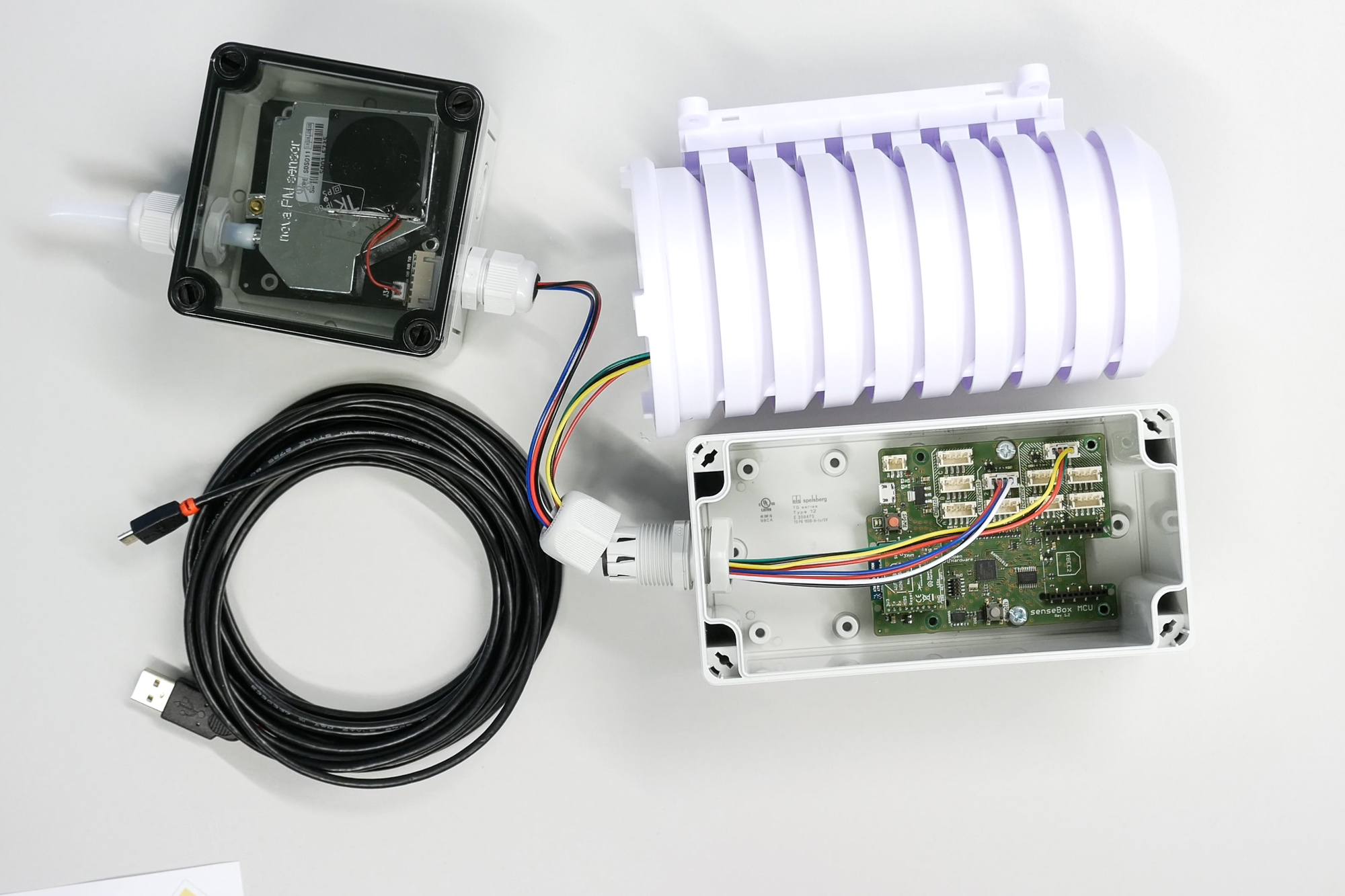
Finally, we connect the micro-USB cable, which is used to program the microcontroller and to supply the senseBox with power later during operation. Please note that the micro-USB port is sensitive and is also subject to the leverage of the cable. For this reason, the USB cable should not be torn later.
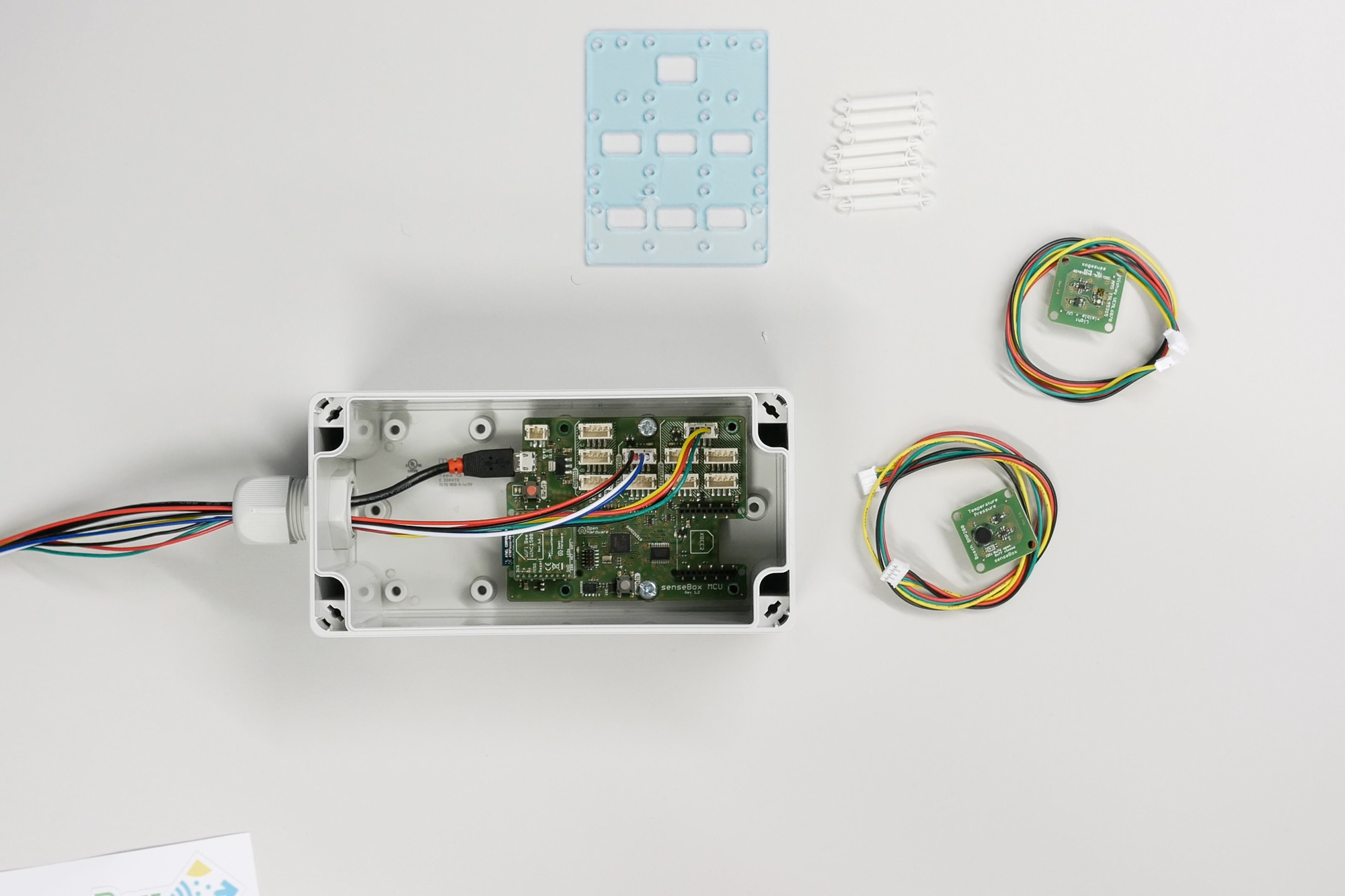
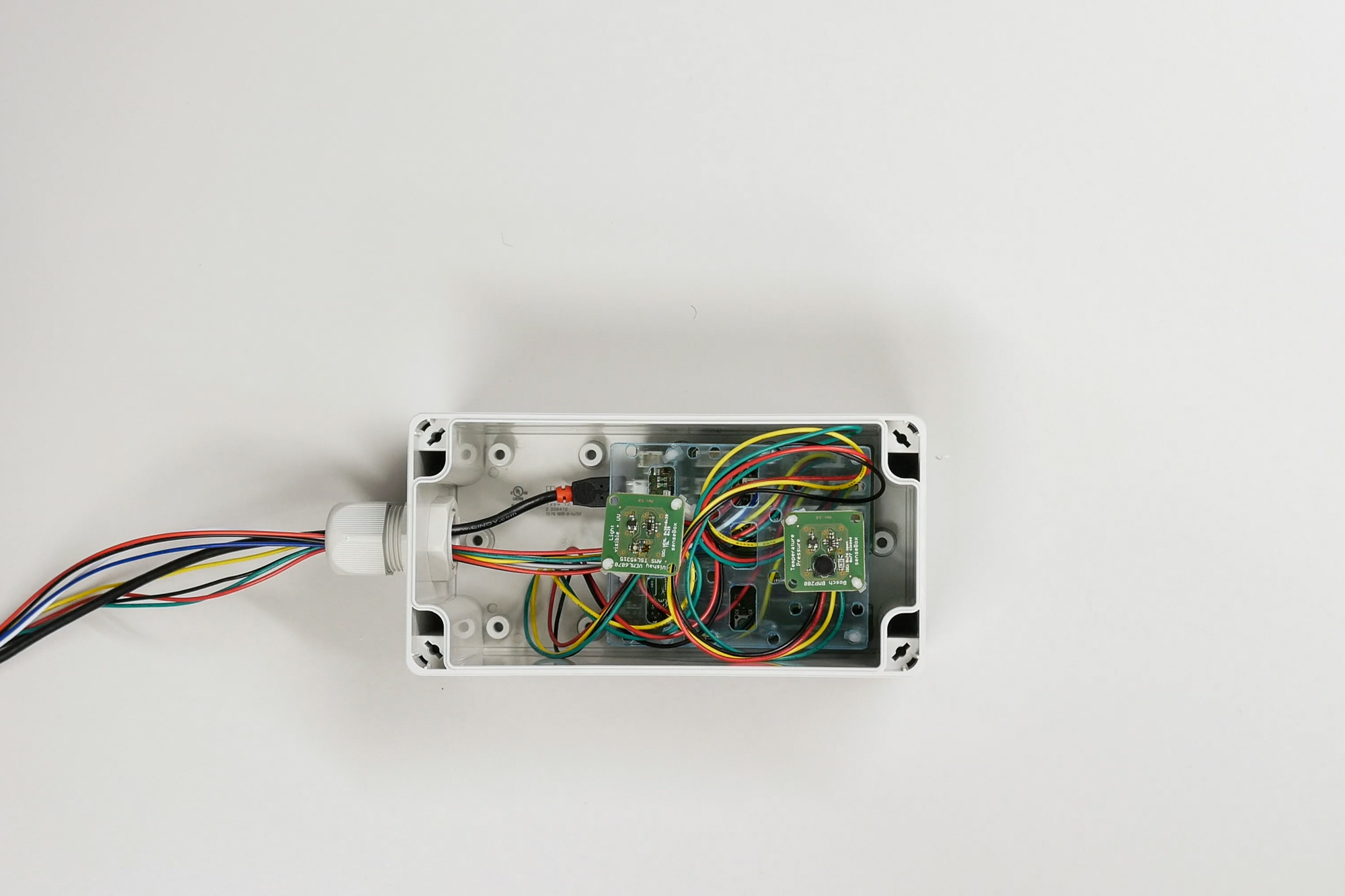
After the outer sensors are connected, the remaining sensors are mounted inside the housing.
A mounting level is constructed for this purpose. First, four spacers are inserted into the external holes of the microcontroller.
The spacers have a grid mechanism. Therefore, if they have to be loosened, they should not be torn out by force, but slightly pressed in at the head.
Afterwards we connect two senseBox cables to the I2C/Wire slots to attach the air pressure sensor and the light sensor.
The cables are threaded through the middle recesses of the mounting plate.
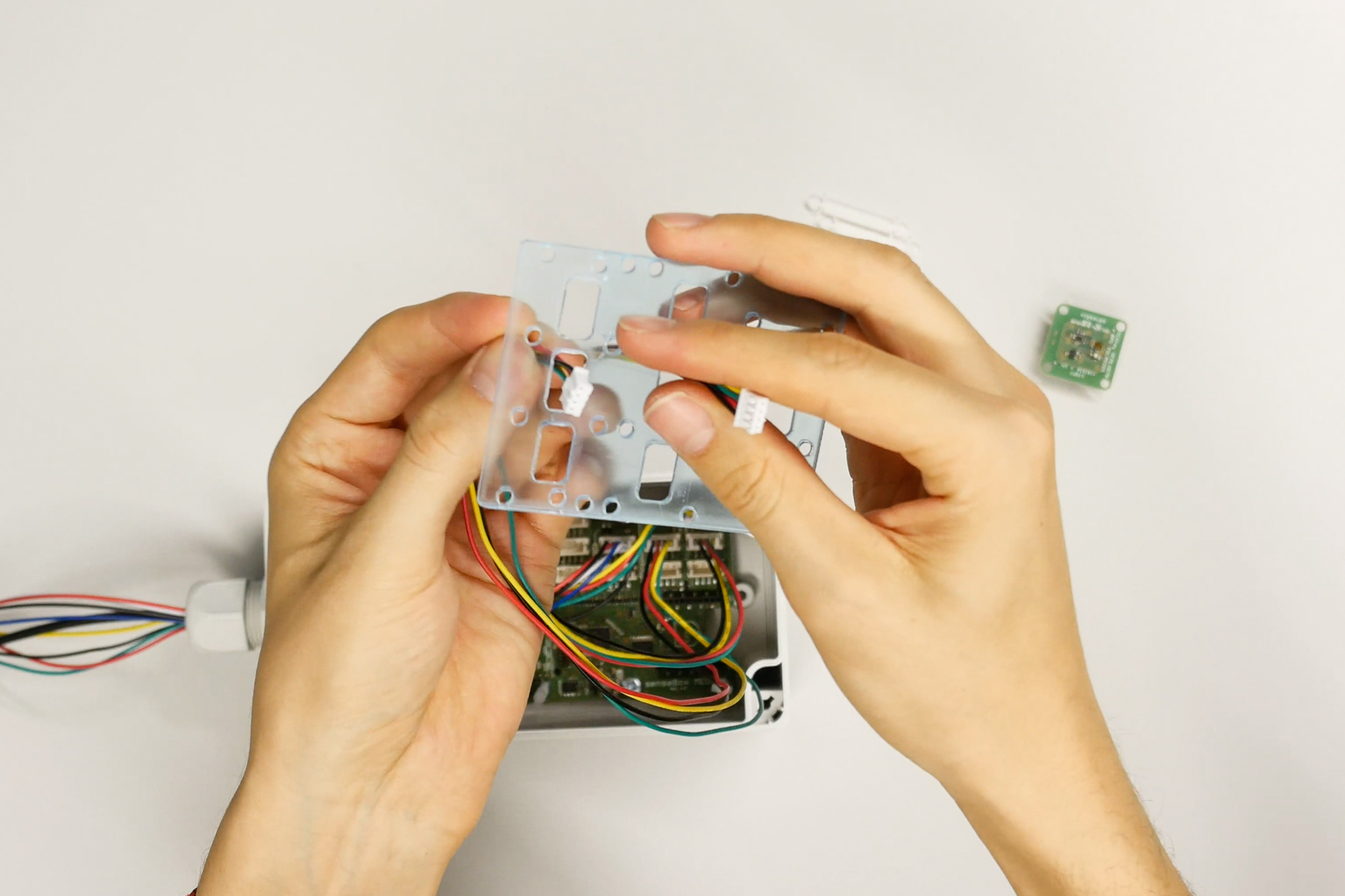
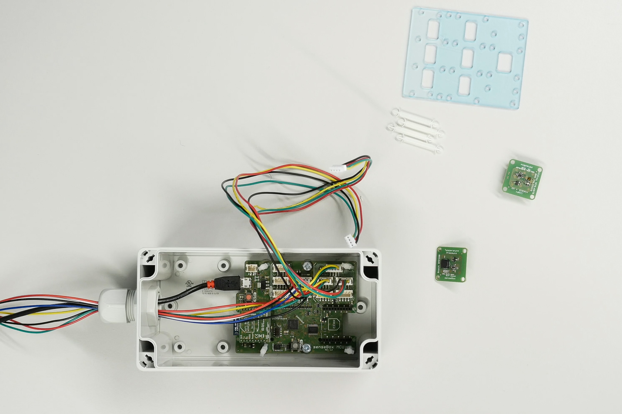
Then the mounting plate is pressed onto the spacers and the cables are connected to the sensors. The sensors are each equipped with two spacers and fastened to the mounting plate. If you have chosen a light sensor, it should be placed as centrally as possible in the housing to obtain good measured values. The air pressure sensor can be placed in the outer slot.
Finally, the cover is fitted with the screws and a silica gel bag is placed inside the housing for further protection against moisture.
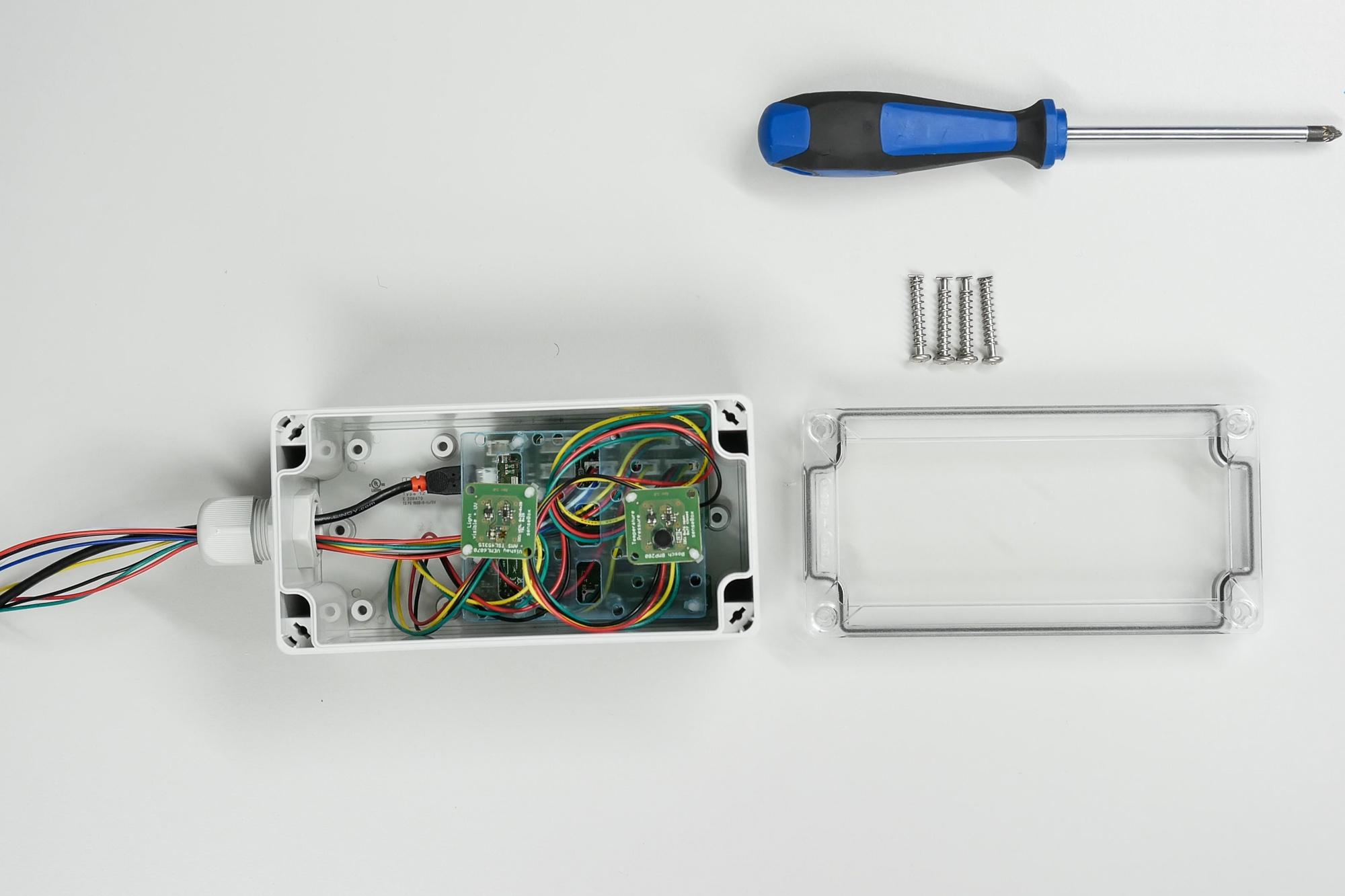
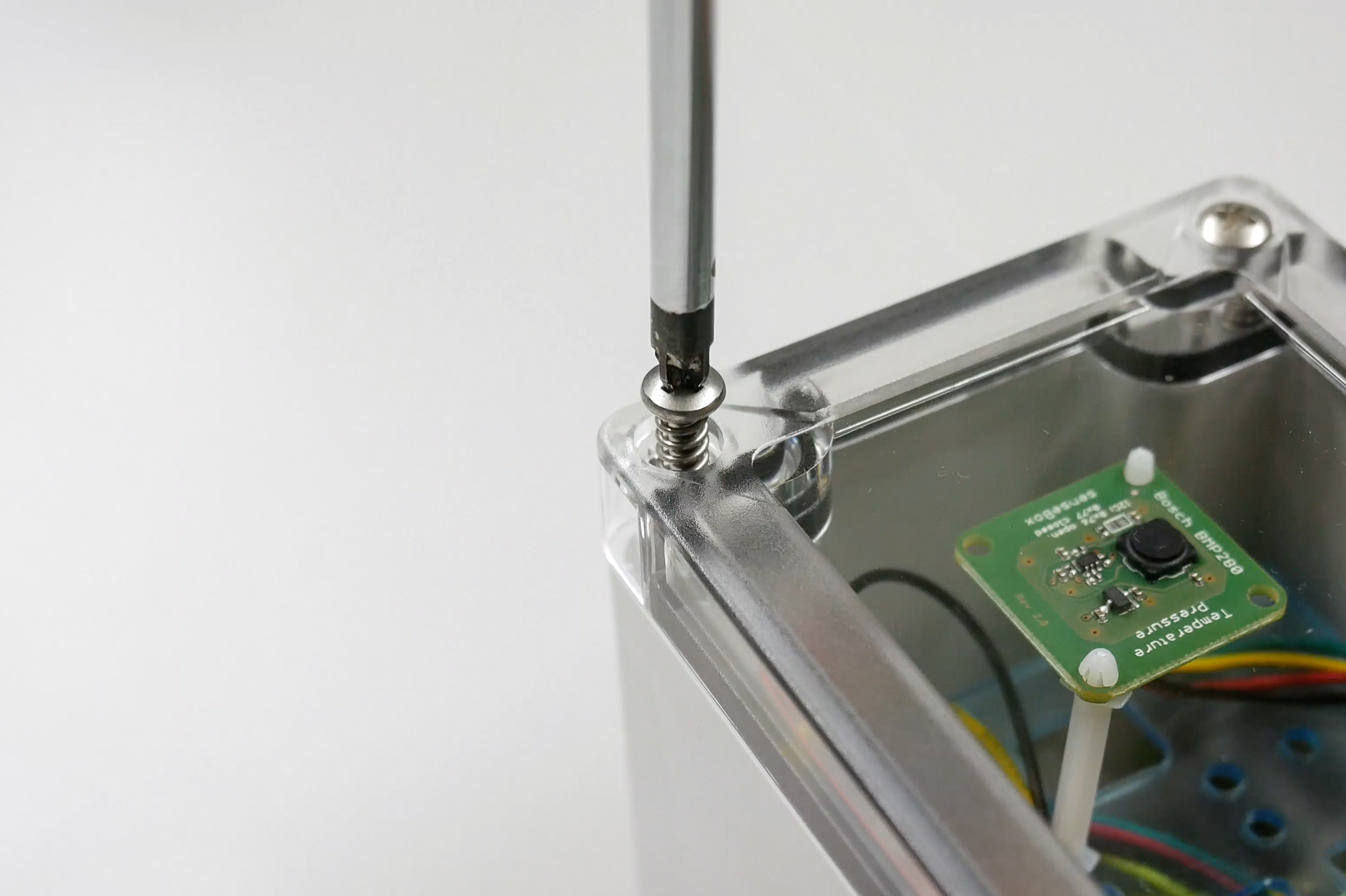
Now the quick release screws are screwed in and the senseBox is closed.
Verschiedene weiterführende Anleitungen für die senseBox:home
Step 1 for setting up the senseBox:home.
Step 2 for building the senseBox:home
Step 3 for building the senseBox:home
Assembly of the senseBox:home in German language